Raspberry Pi Accessories: Piezo Speaker, Poweroff LED, Switch, Blinkt
In this post, I describe four accessories added to my Raspberry Pi 3.
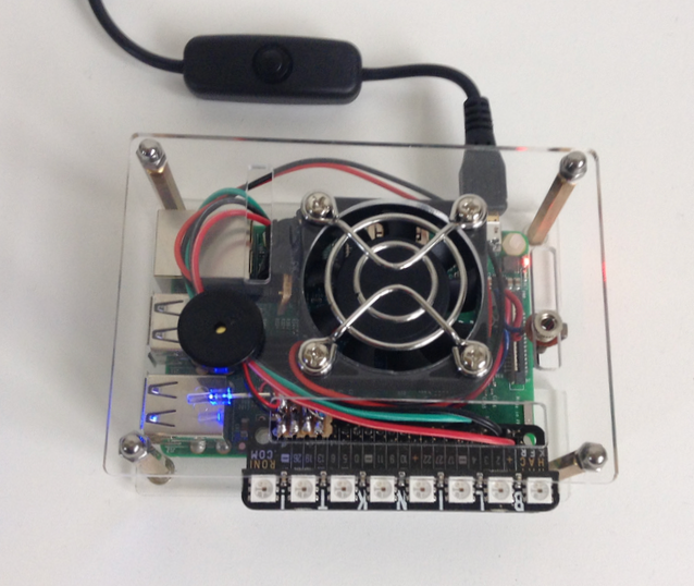
To the left of the fan, mounted on top of the case, is a piezo speaker element, for producing tones and low-fidelity musical melodies. Below the piezo speaker is a small blue LED which indicates when the Raspberry Pi has been shut down and power can be safely removed. To the right of the fan is a 3/32" mono phone jack mounted in a slot in the case top, to which an input switch can be connected:
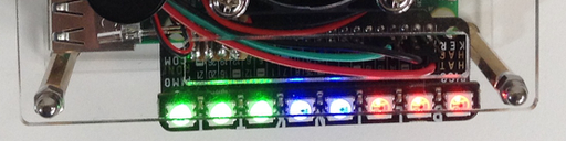
Extending beyond the lower edge of the case is the Pimoroni Blinkt! module (available in the US from Adafruit), a nifty unit containing 8 multi-color LEDs:
Hardware
I wanted a setup that was cleaner than having multiple jumper wires flowing out of the Raspberry Pi over to a breadboard, into which tentatively-connected components were plugged. So I put together a small circuit board that could attach directly to the GPIO pins (via a 4-pin header) and fit entirely within the case.
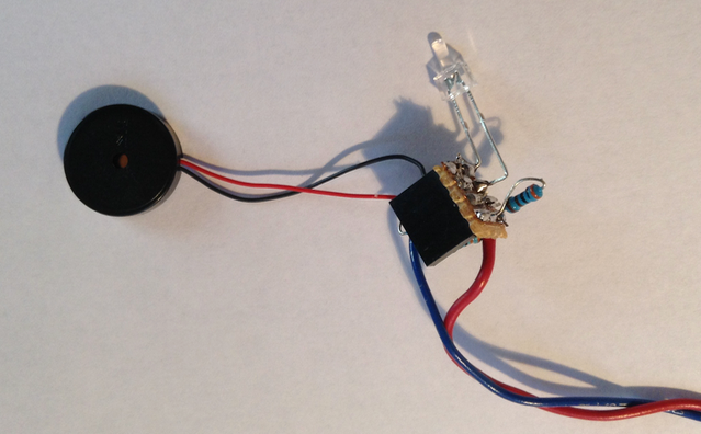
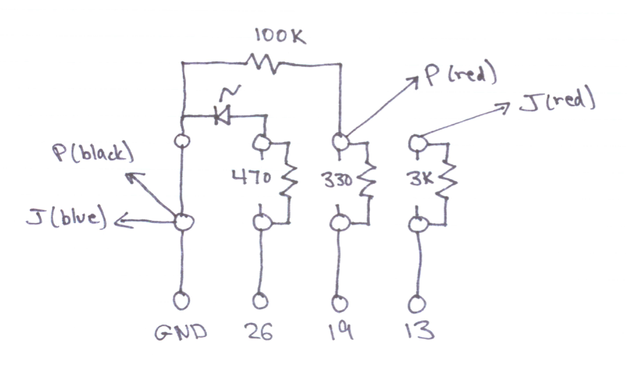
The stripboard layout is shown on the right. I kept it to a 3x4 array of holes, so that the board could fit in between the cooling fan and the GPIO connector. The LED and one resistor are attached to the upper (copper-strip) side of the board, and the other three resistors are attached on the lower side. Three of the copper strips were cut between pairs of holes. This is a little trickier than the usual method of using a drill bit on one entire hole when it is necessary to cut a strip. I used an Exacto knife to make two parallel cuts in a strip, and then I used an awl to scrape out the copper in between.
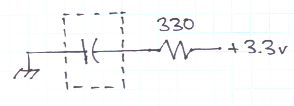
The LED circuit is shown below:

With a 3.3v GPIO pin output and the small blue LED having a voltage drop of 2.6v, the voltage across the 470 ohm resistor current-limiting resistor is 0.7v thus giving an LED current of 1.5 mA. This is a little low for getting full brightness from a blue LED, but it was completely adequate for this one when used as an indicator.
The web page here seems to be the best source of information regarding Raspberry Pi GPIO electric limits. A current of 1.5 mA is also comfortably below the 8 mA limit given on that page as the default continuous-current limit for GPIO output from one pin.
The piezo speaker circuit is shown below:
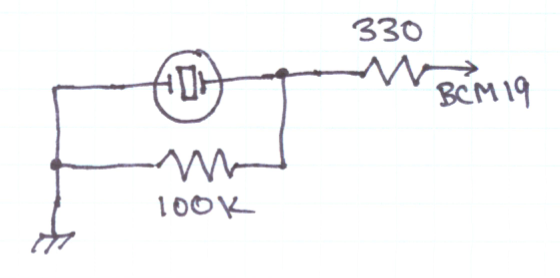
Brave souls might attach the piezo element directly to the GPIO pins, without any resistors. Although that might work out OK (and it is often shown that way with similar Arduino projects), I was hesitant to do so, given the more electrically-fragile nature of the GPIO connections.
When the piezo element is used as a speaker, and modelled most simply as a capacitive load, the main concern is to limit transient currents from a GPIO pin to 16 mA or less. This is accomplished by the 330 ohm series resistor, which limits the current at 3.3v to 10 mA.
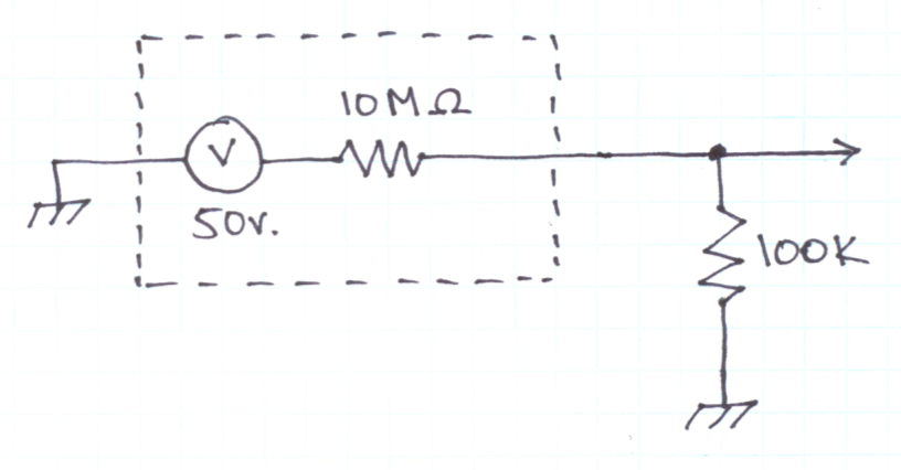
A piezo element can also be used as a sound transducer. Arduino applications often use these as knock sensors. Although in this case I was only interested in the piezo as a speaker, it is still the case that a tap on the piezo element could generate a potentially damaging voltage spike.
The appropriate model in this case is to treat the piezo element as a voltage source with a very high output impedance. The 100k ohm parallel resistor makes a voltage divider that reduces a typical output voltage of 50v from the element to about half a volt at the GPIO pin input. (Arduino circuits usually specify a 1 megohm resistor here, for the purpose of bringing a 50v peak down to the 5v maximum range of the Arduino ADC pins.)
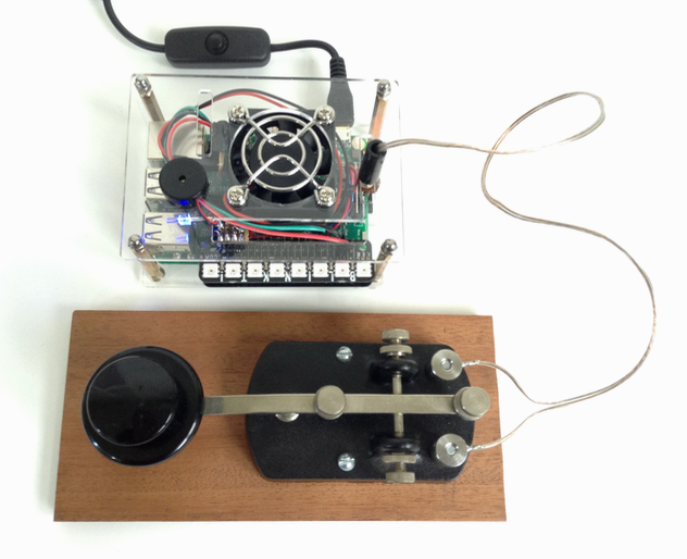
The switch circuit connected to a tiny phone jack, which just barely fit in a pre-cut slot in the top part of the case. I could have drilled a hole in the case top and installed a push-button, but the jack allowed for multiple options and didn't involve marring the acrylic sheet. Suggested circuits usually just connect a switch between a GPIO pin and ground. That is fine if the GPIO pin mode is always set to input, but I didn't like the potential for a short-circuit to ground if the pin happened to be set to high output and the switch were closed. This potential problem is eliminated with the addition of a 3k ohm series resistor:

If the pin is set to input with the internal pullup resistor enabled, then closing the switch brings the switch down to a voltage of about 0.2v, assuming a pullup resistance of 50k ohm or so. This is well under the level that is interpreted as a digital zero.
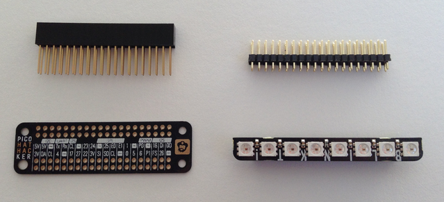
The Blinkt! module is designed to fit directly on the entire GPIO connector, which makes for a very compact installation but prevents any other use of the GPIO pins. Pimoroni and Adafruit sell a little board called the "Pimoroni Pico HAT Hacker" that, with the appropriate headers, duplicates the GPIO header so that one entire set of pins can be used for the Blinkt! and another duplicate set can be used for any other purpose:
Software
Testing the hardware
The following assumes that Raspbian Stretch is installed, along with the WiringPi library. To verify that WiringPi is installed, check the version as follows:
$ gpio -v
gpio version: 2.44
Copyright (c) 2012-2017 Gordon Henderson
This is free software with ABSOLUTELY NO WARRANTY.
For details type: gpio -warranty

Raspberry Pi Details:
  Type: Pi 3, Revision: 02, Memory: 1024MB, Maker: Embest
  * Device tree is enabled.
  *--> Raspberry Pi 3 Model B Rev 1.2
  * This Raspberry Pi supports user-level GPIO access.
The first tests of the switch and the LED can be accomplished via the WiringPi command line tool:
# set up GPIO pin BCM 26
gpio -g mode 26 out

# turn on LED
gpio -g write 26 1

# turn off LED
gpio -g write 26 0

# set up GPIO pin BCM 13
gpio -g mode 13 in
gpio -g mode 13 up

# read status of switch when open
gpio -g read 13

# read status of switch when closed
gpio -g read 13
To test the piezo speaker, use the following C program, which plays a 5 second tone.
Create the source file:
vi tone.c
Insert text:
#include <wiringPi.h>
#include <softTone.h>

int main(int argc, const char * argv[])
{
#define PIN 19
#define FREQ 500
#define MSEC 5000

    wiringPiSetupGpio();

    pinMode(PIN, OUTPUT);
    softToneCreate(PIN);

    softToneWrite(PIN, FREQ);
    delay(MSEC);
    softToneWrite(PIN, 0);

    return 0;
}
Save, compile, and run:
gcc -o tone tone.c -lwiringPi -lpthread
./tone
Code practice buzzer
The following C program plays a tone through the piezo speaker whenever a switch attached to the jack is closed.
Create the source file:
vi codebuzzer.c
Insert text:
#include <wiringPi.h>
#include <softTone.h>

int main(int argc, const char * argv[])
{
#define KEY_PIN 13
#define SPEAKER_PIN 19
#define FREQ 750

	int keydown = 0;
    wiringPiSetupGpio();

    pinMode(KEY_PIN, INPUT);
    pullUpDnControl (KEY_PIN, PUD_UP);
    pinMode(SPEAKER_PIN, OUTPUT);
    softToneCreate(SPEAKER_PIN);

    while (1) {
    	int next_keydown = digitalRead(KEY_PIN) == 0;

    	if (keydown != next_keydown) {
    		keydown = next_keydown;
    		softToneWrite(SPEAKER_PIN, keydown ? FREQ : 0);
    	}
    }

    return 0;
}
Save, compile, and run. Type Ctrl-C to halt.
gcc -o codebuzzer codebuzzer.c -lwiringPi -lpthread
./codebuzzer
Poweroff indicator LED
To enable pin 26 as the indicator for the Raspberry Pi poweroff state, use the following command:
sudo dtoverlay gpio-poweroff active_low=0
(Pin 26 is default choice for the gpio-poweroff overlay.)
To activate the overlay automatically when the Raspberry Pi is turned on, edit the
config.txt file:
sudo vi /boot/config.txt
add the line following after the comment:
# Additional overlays and parameters are documented /boot/overlays/README
dtoverlay=gpio-poweroff,active_low=0
and reboot:
sudo reboot
mbeep for GPIO
The mbeep tool plays tones, MIDI notes, or Morse code on the default audio device. I created a patched version that generates tones by toggling a gpio pin, which is assumed to be connected to a piezo speaker element or similar device.
To build the patched version, use the following steps (which assume the piezo speaker is attached to gpio pin BCM 19):
git clone https://github.com/7402/mbeep.git
cd mbeep
make GPIO=19
./mbeep --man-page > mbeep.1
sudo make install