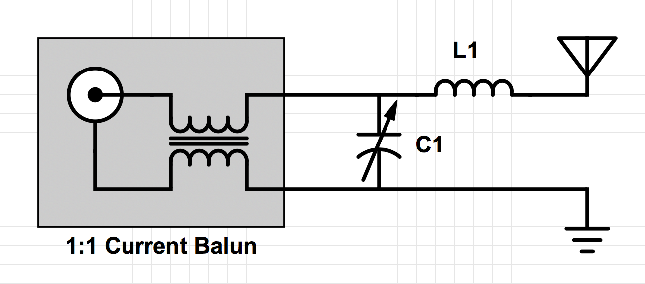
Antenna tuner peg board for sash window
My Amateur Radio 5 watt CW transceiver (the LNR Mountain Topper MTR3B) transmits on 40, 30 and 20 meters, so I wanted to be able to use my antenna on those bands.
My fairly lousy HF antenna situation is as follows:
Antenna
- An end-fed wire antenna, running about 50 feet from my radio room's window to the edge of the lot.
- About 17 feet up at the highest point.
- Turns several corners.
- Runs within just a few feet of a gutter, a fence, a big tree, and the roof of the garage.
- Below the level of the house roof.
- Overshadowed by an 60-foot-tall oak tree.
Ground
- A single buried ground wire, running a few inches underground for about 30 feet.
- The ground wire is tied to a random drain pipe sticking up a foot out of the ground under the shack window.
- The "ground" wire then runs up about 10 feet to the shack window.
- Note that this is not a proper grounding arrangement for any equipment in any way connected to the house AC voltage. All rigs in use are 100% battery-operated and 100% independent of any other household circuits.
Optional Counterpoise / Alternate Antenna
- A 100 foot wire, attached to the property fence.
- The wire is attached near the top of the fence, about 5 feet above the ground.
- The wire makes two 90-degree turns, to make a square-U shape.
- Each side is about 35 feet or so.
With a situation like that, I knew that I would need a flexible antenna tuner, one that would be compatible with easy experimenting. It would not do just to select component values based on an ideal theoretical antenna and hope that they worked.
Although I leave it up for months at a time, the antenna is basically a temporary setup, so I did not want to make any permanent changes to my house. The radio room has sash windows, so I chose to make a feed-through board that would fit in the top gap that appears when the upper sash is opened a few inches. By placing two rows of wood screws across most of the length of the board, I created a peg board on which I could mix and match various components as needed.
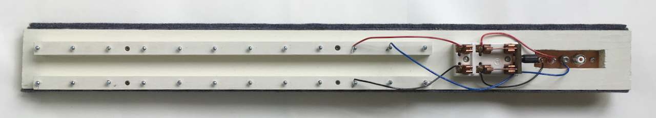
Most of the board is taken up by two attached pieces of 3/4 inch square dowel stock. A 2 x 12 array of round-head screws are placed in the square stock with uniform 2 inch spacing. The screws are not screwed-in all the way; there is a small gap left so that components can hook over the edge of the head.
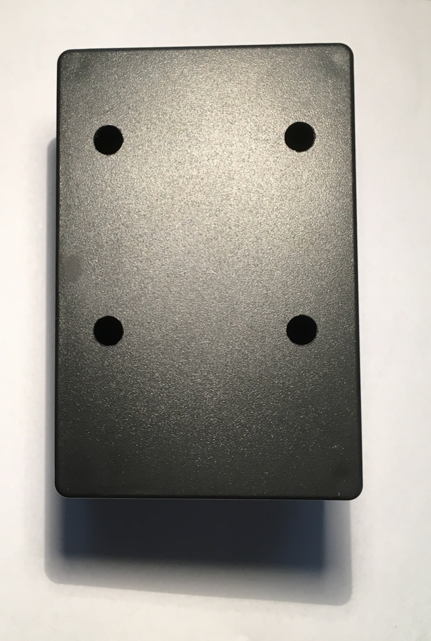
Most of the components are installed in small plastic project boxes. The boxes have holes drilled in the back so they can hook onto the board.
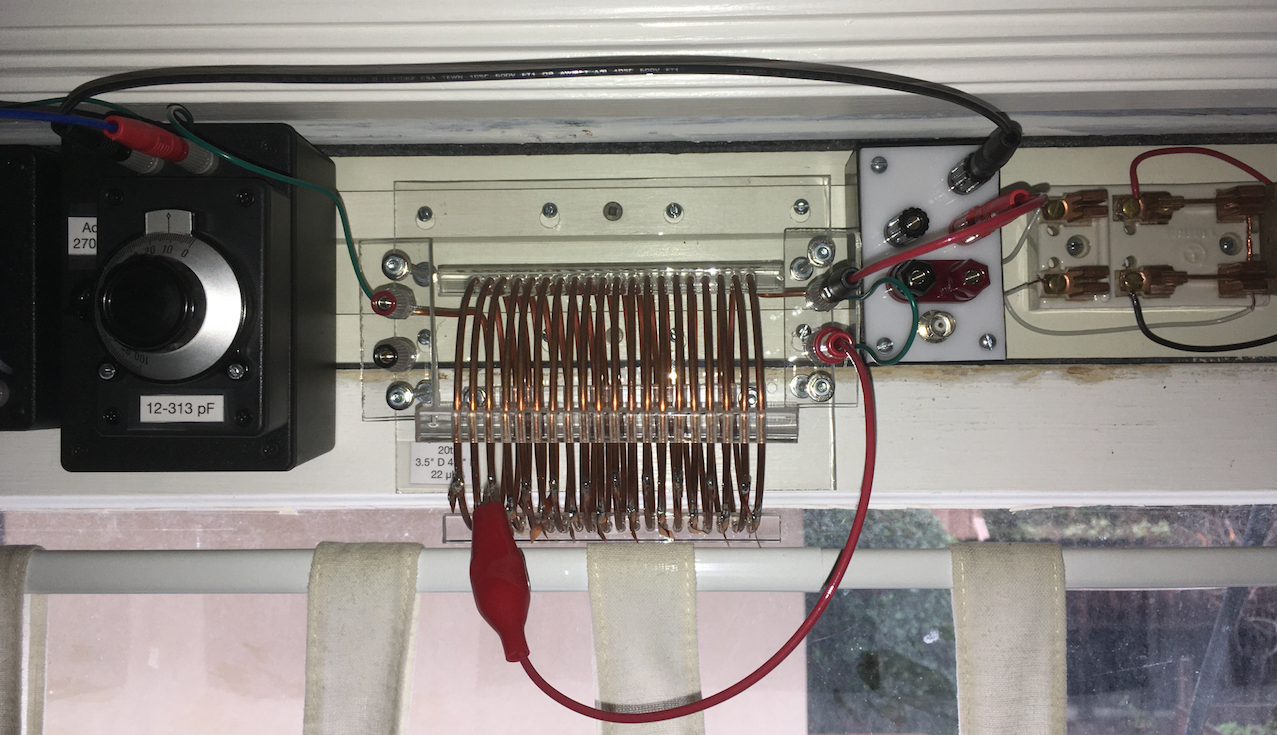
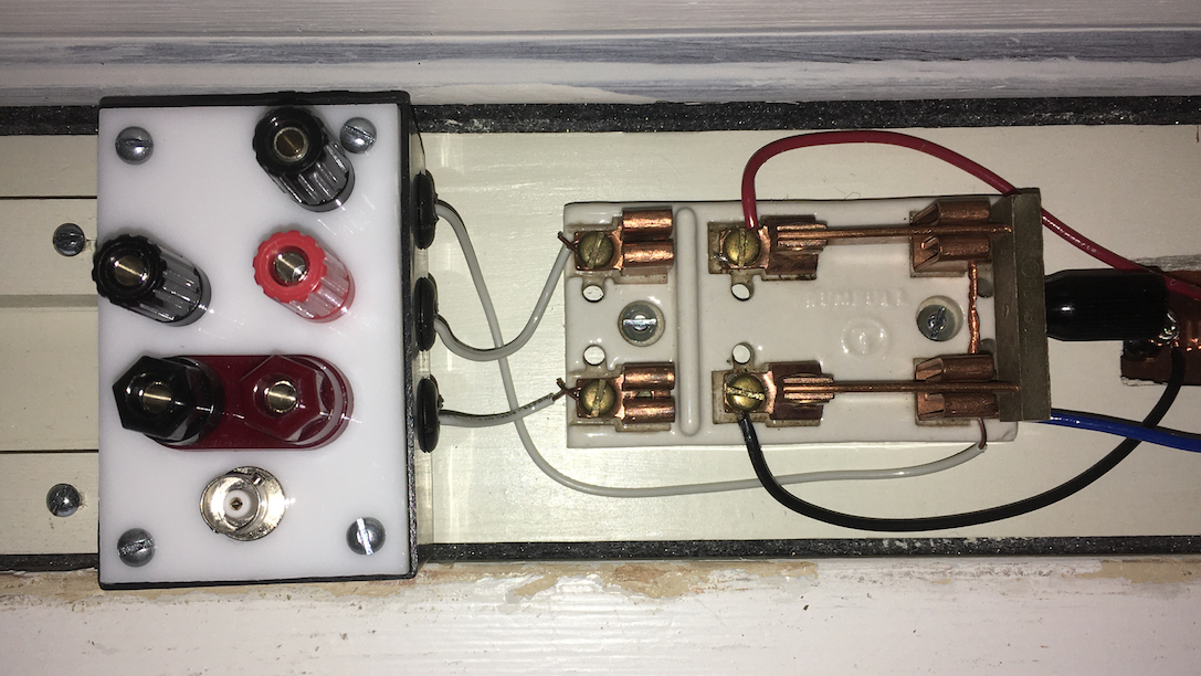
Here is the board in use. The parts from left to right are: 1:1 current balun, variable capacitor, coil, connector box, porcelain DPDT knife switch, copper feed-through plate.
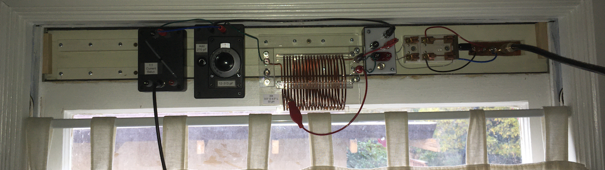
The BNC connector at the bottom of the balun leads to the transceiver:
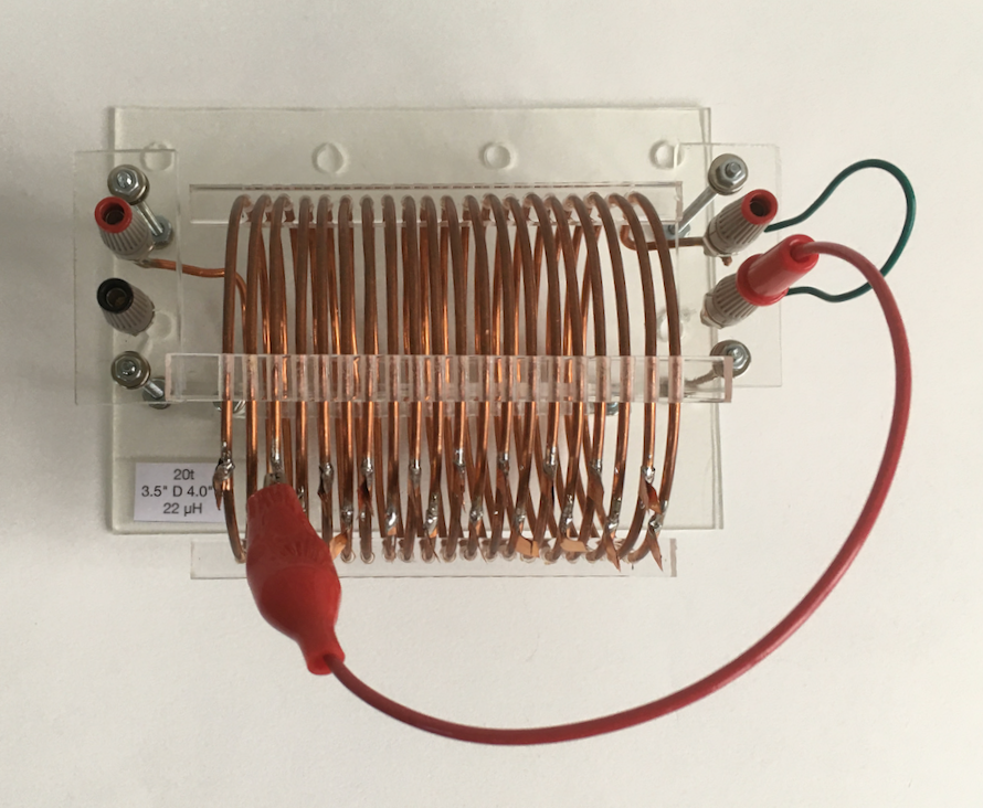
The red jumper is used to short out different lengths of the coil to vary the inductance:
The 2" x 3.5" porcelain antenna switch was an eBay find ($21). The feed-through plate was a 2" x 5" x 1/16" piece of copper ($7), also from eBay:
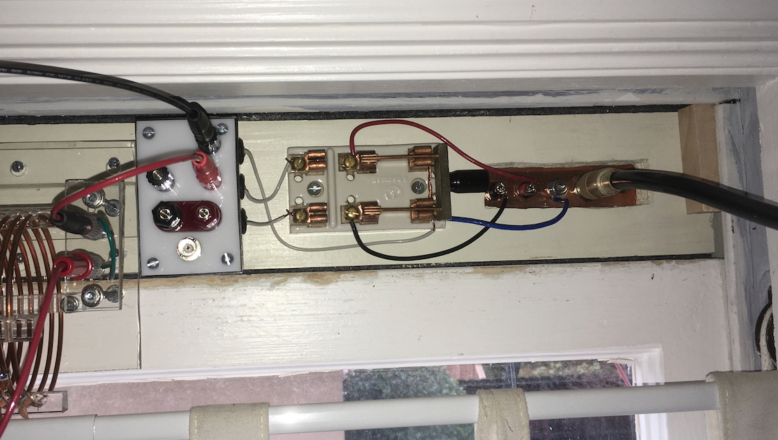
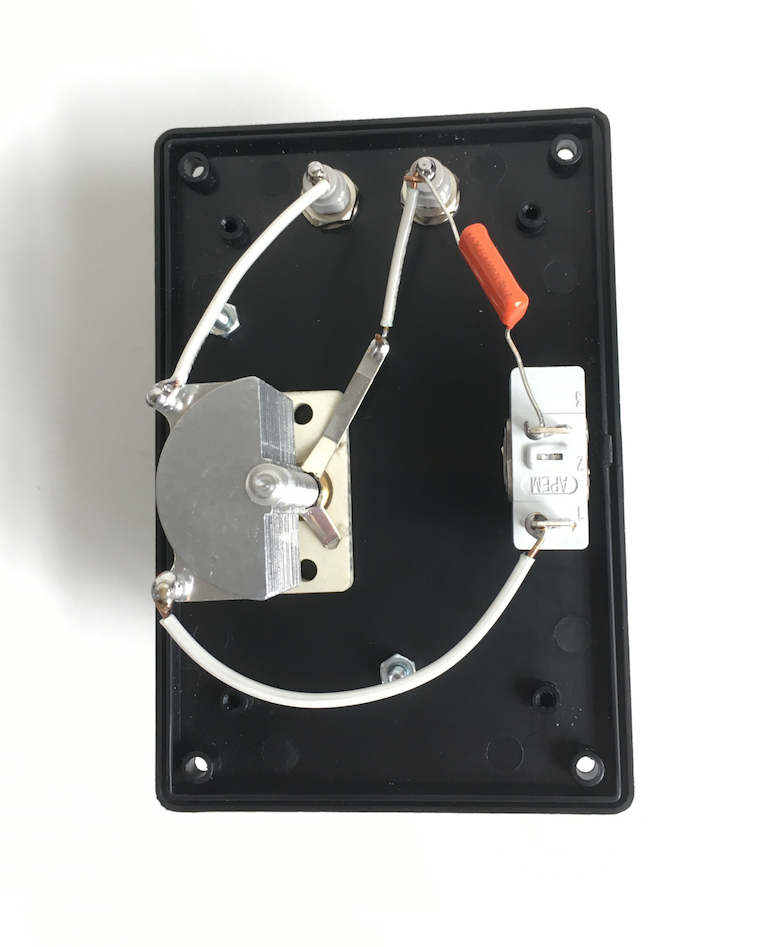
When the knife switch is thrown to the right, the antenna and counterpoise are both grounded. When the knife switch is thrown to the left, the antenna is attached to the red binding post on the connector box and the counterpoise wire is attached to the left black binding post. The ground is always attached to the upper black binding post. (The BNC connector and lower binding post pair are attached to each other, but not to anything else.)
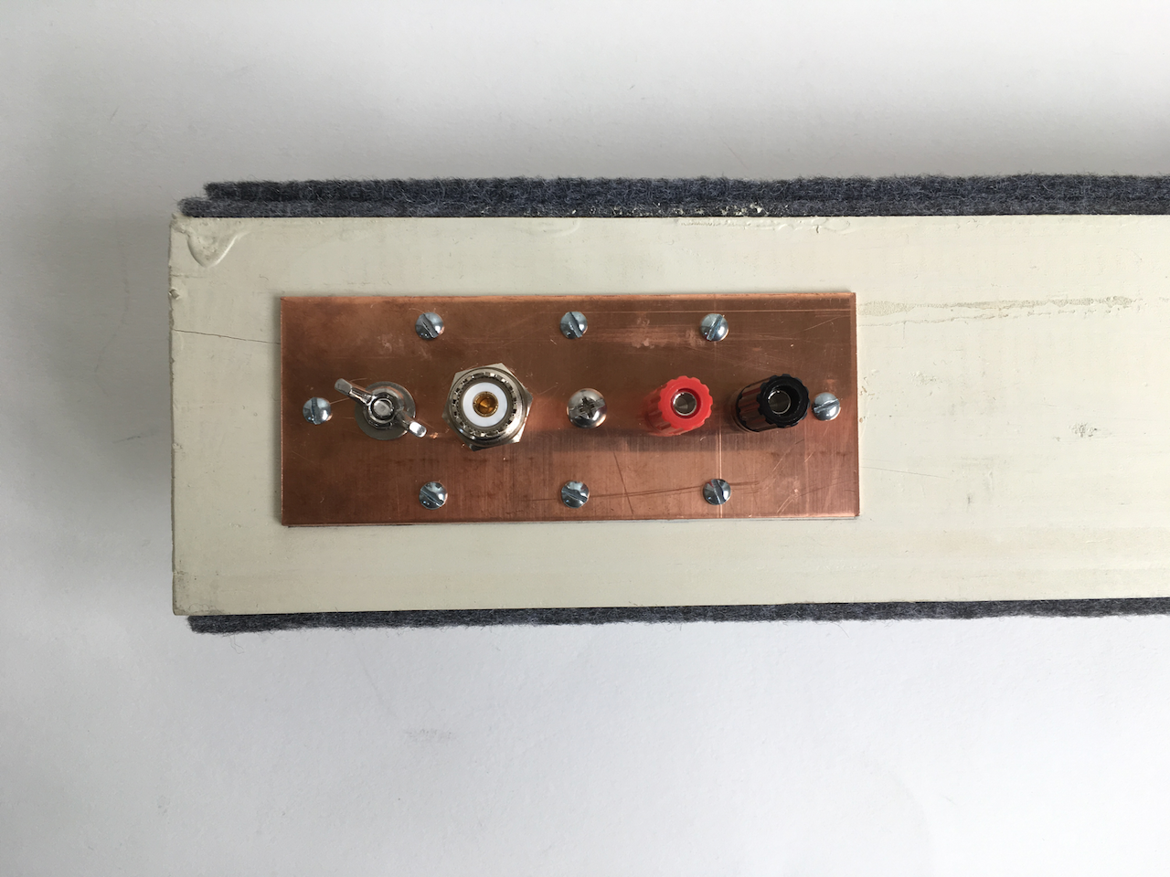
The copper feed-through plate has connections for counterpoise, antenna, ground, and a dual-ended SO-239 socket for a separate 2 meter / 440 MHz vertical.
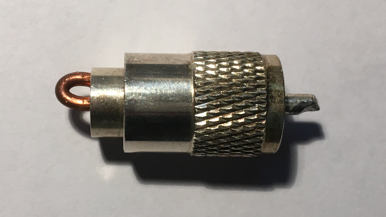
When the VHF / UHF antenna is not in use, I stick a grounding PL-259 plug into the inside SO-239 on the plate.
The outside of the feed-through plate uses binding posts or a stainless steel wing nut for attaching the wires.
Components
Connector box and knife switch (permanently mounted):
Inductor, consisting of 20 turns of 10 AWG copper wire. Full inductance is 22 μH.
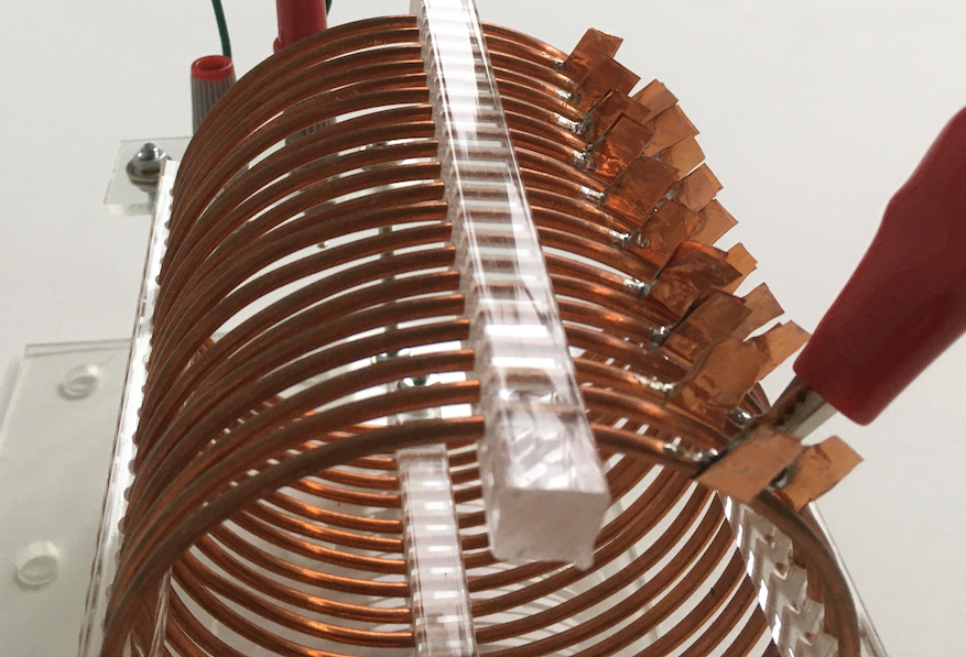
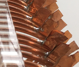
The coil has little copper tabs extending out in an alternating pattern, to make it easy to place the shorting clip without shorting adjacent turns:
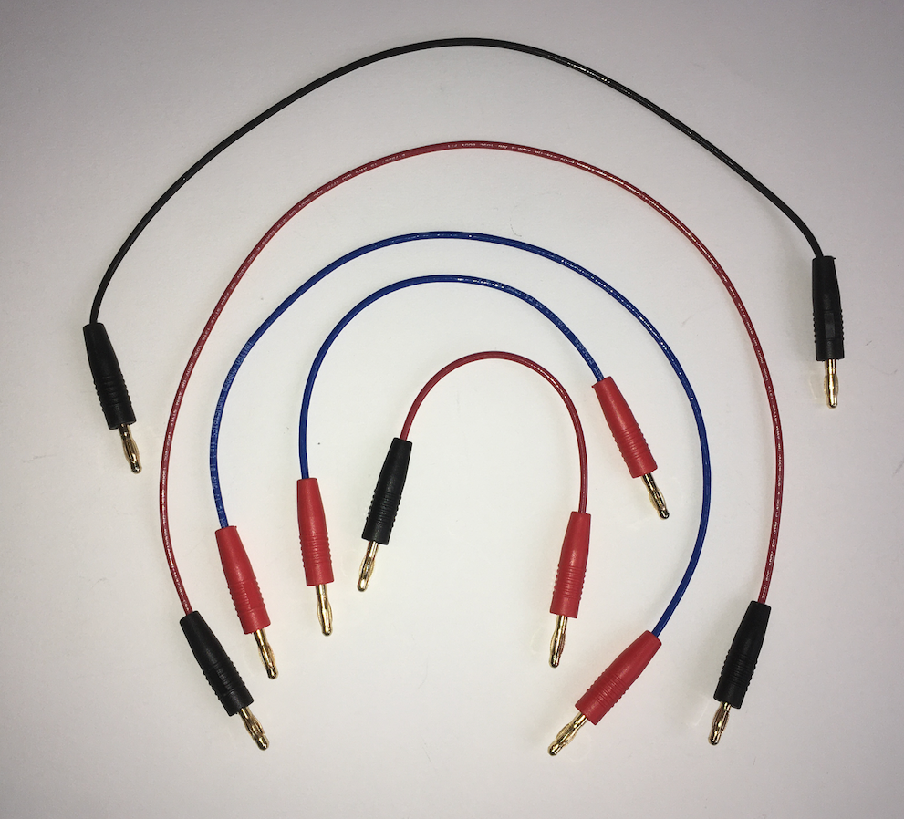
Assorted jumpers with banana plugs, to plug into the binding posts. The binding posts can also take plain wires, if necessary, but the banana plugs allow for quick configuration changes.
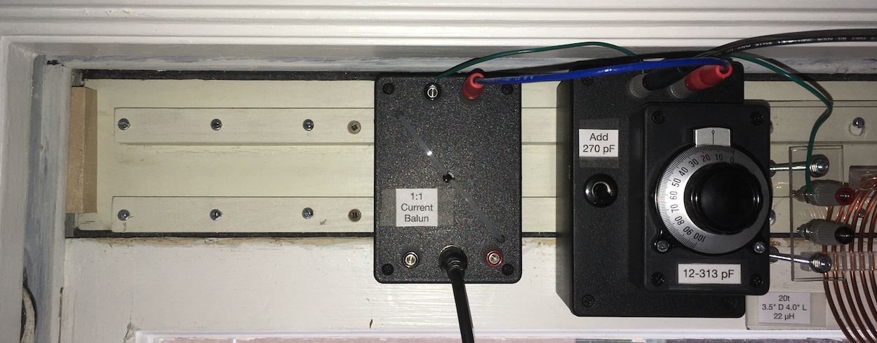
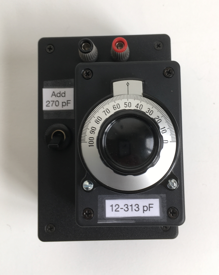
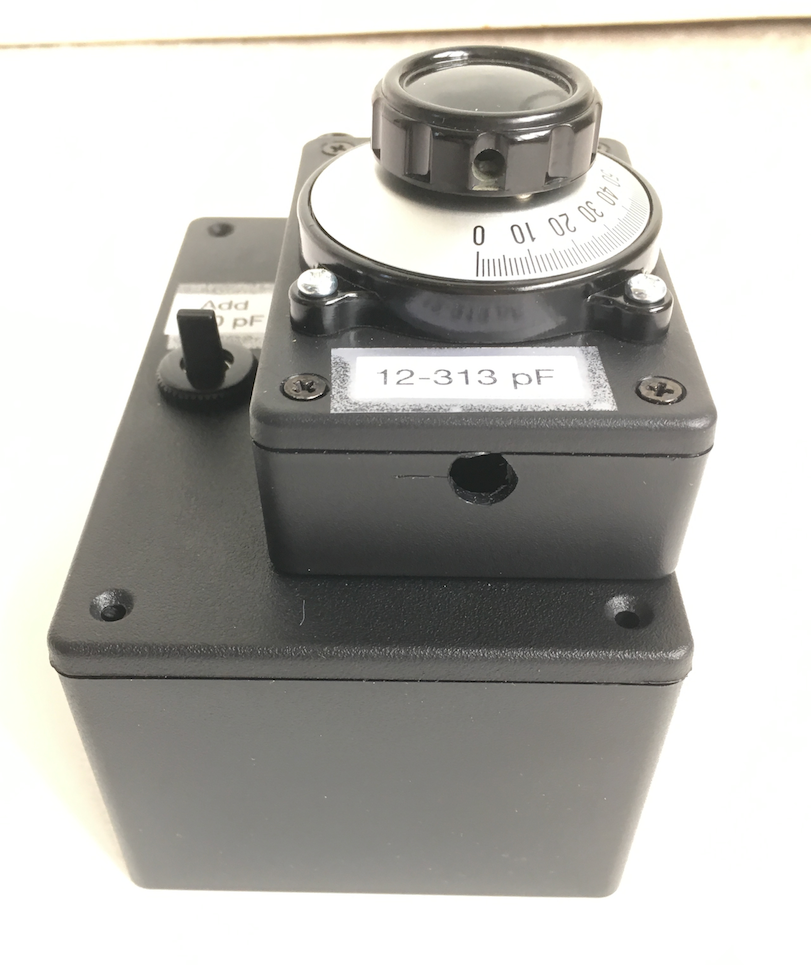
Variable capacitor (12 to 313 pF), with option to add in an additional 270 pF, for a total range of 12 to 583 pF. I made two of these, in case I wanted to try a pi-match network, in addition to the simpler L-match.
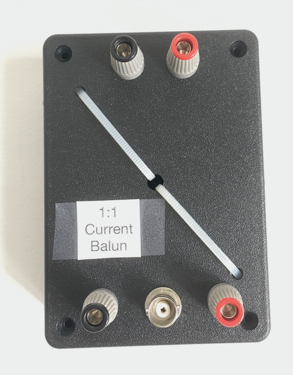
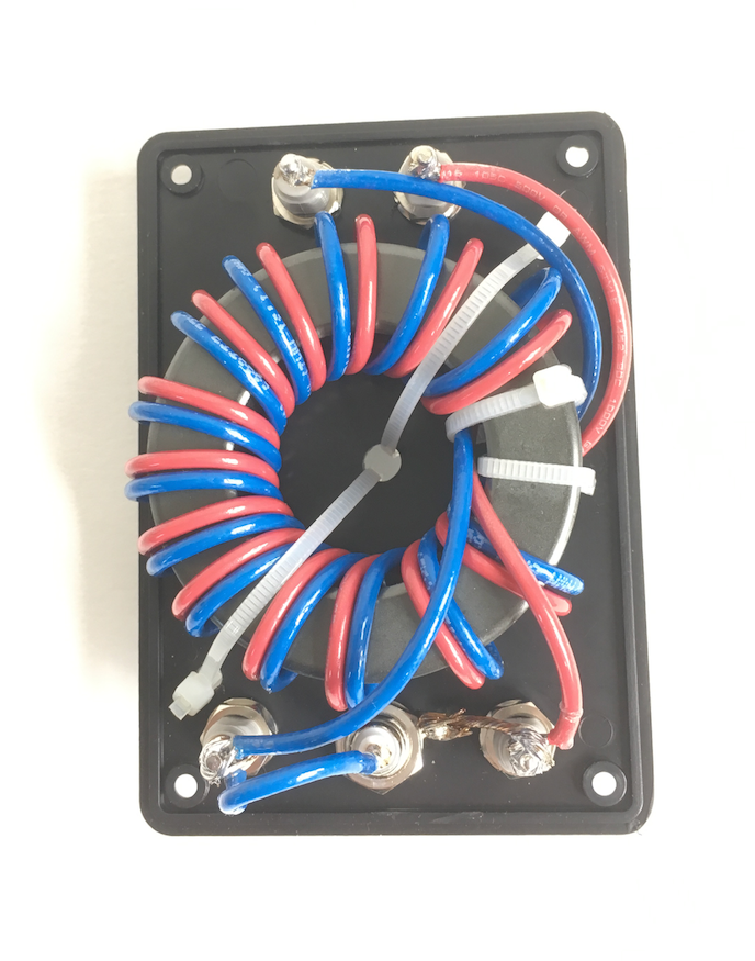
A 1:1 current balun, wound on a toroid. Either the binding posts on the bottom or the BNC connector can be used for the output.
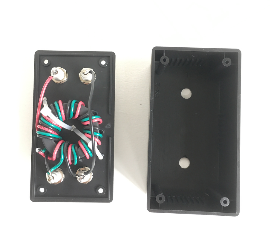
A 9:1 unun, wound on a toroid.
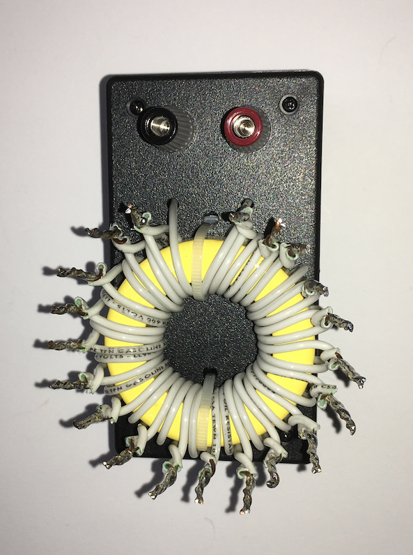
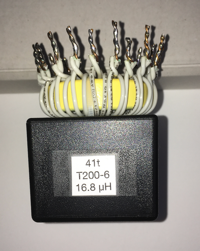
A 16.8 μH toroidal inductor, with multiple taps for reduced inductance.
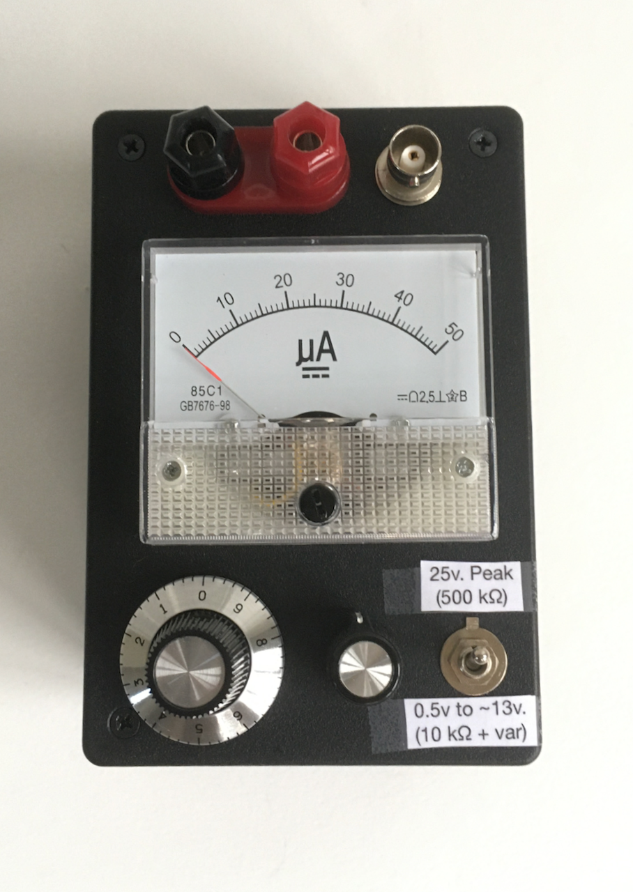
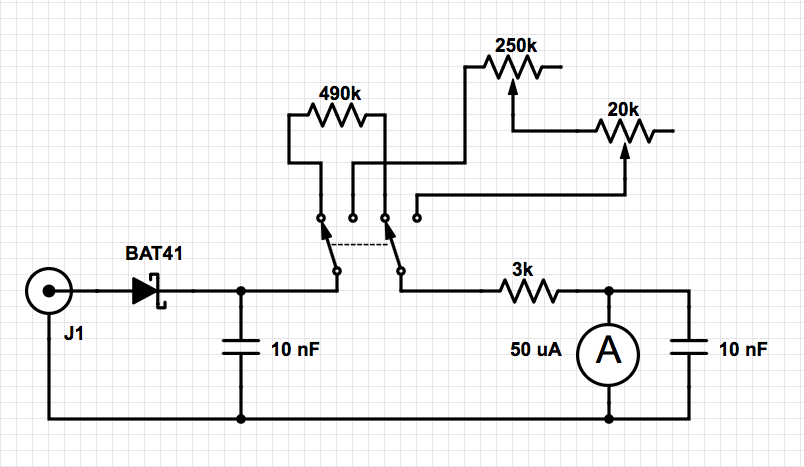
A flexible RF voltmeter that can be adapted for various uses, such as a QRP power meter.
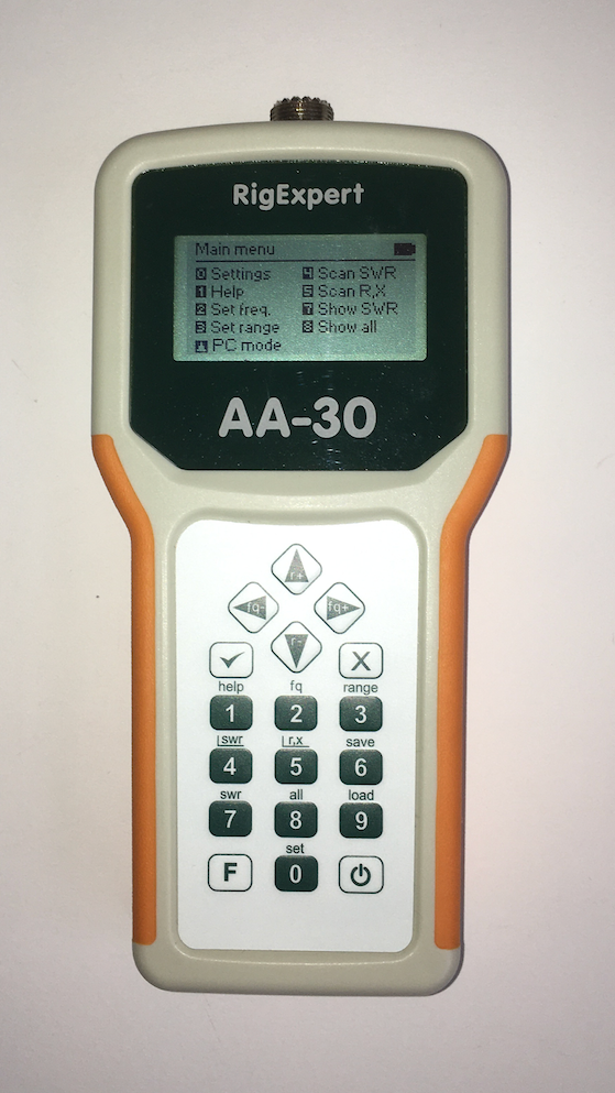
I found this antenna analyzer, the RigExpert AA-30, to be hugely valuable in figuring out the state of the antennas and their tuning. Newer improved version (AA-35) runs about $230.
Usage
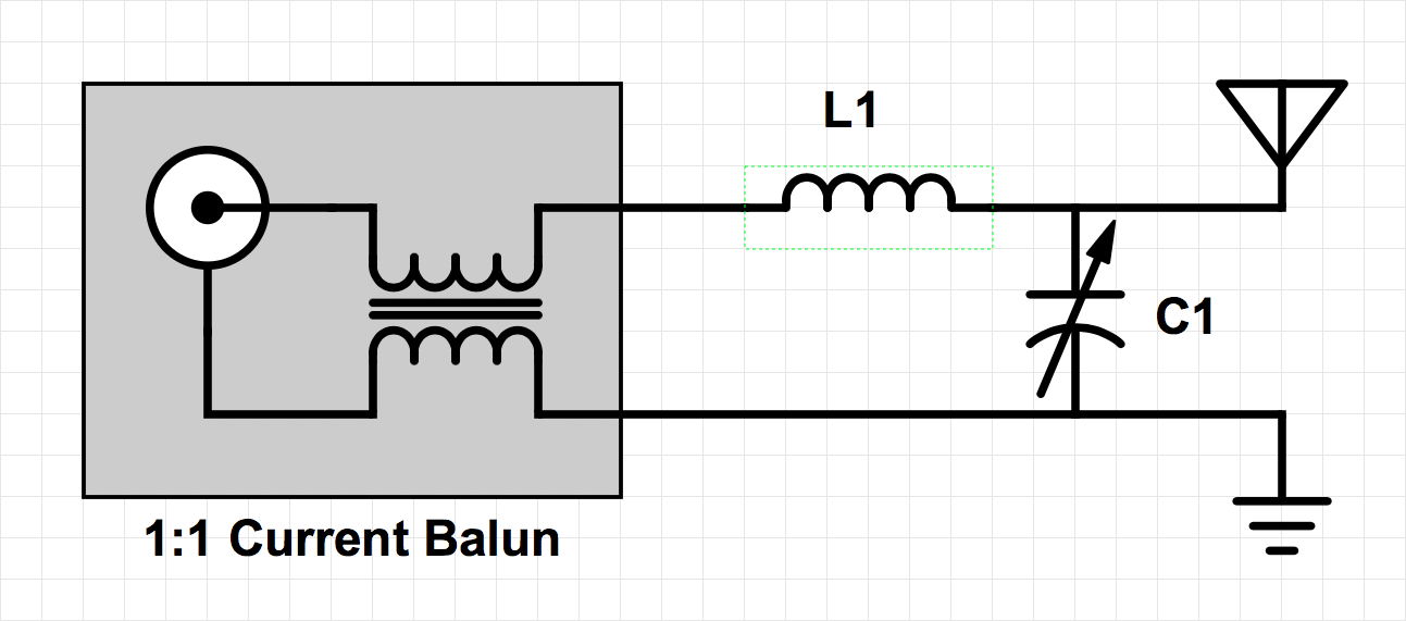
I used this arrangement for 40 and 20 meters. I could also use this when tuning on 80 meters against the 100 foot fence wire.
I used this arrangement for 30 meters.
Construction
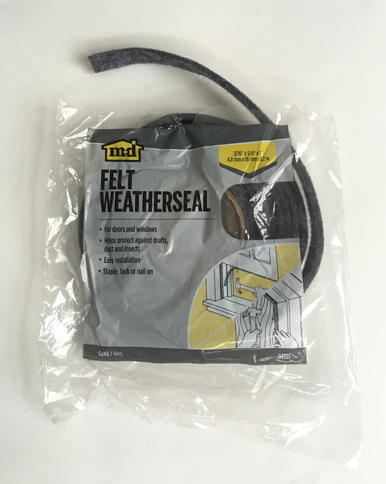
I used standard hardware-store felt weatherstripping on the top and bottom of the board to obtain a snug fit.
Variable capacitor
This component uses an MFJ 282-2006 air variable 12-313 pF capacitor, rated at 640 volts. I added a 270 pF 600 volt fixed capacitor that can be switched in, in parallel.
The vernier dial is a 2" diameter Philmore S-50 from eBay. The hole in the bottom of the box is to give access for tightening the set screw of the dial onto the capacitor shaft.
1:1 balun
This balun is wound with 13 bifiliar turns of 16 AWG 600 volt wire on an FT240-31 toroid.
9:1 unun
This 9:1 unun is wound with 9 trifiliar turns of 16 AWG 600 volt wire on an FT140-61 toroid. Note: although it happens to have 9 turns, that has nothing to do with it being a 9:1 transformer! It is a 9:1 transformer because of the way the three windings are wired.
Coil
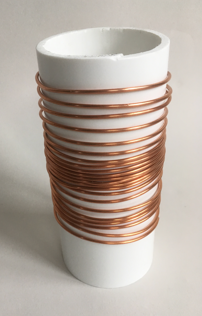
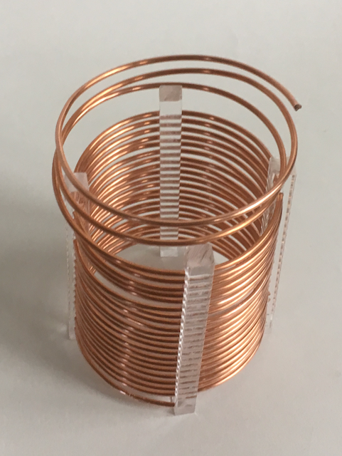
The coil is wound from 20 turns of #10 AWG bare copper, about 20 feet worth from Home Depot.
First, I coiled the wire around a piece of 3.5 inch (o.d.) PVC pipe to set up the shape:
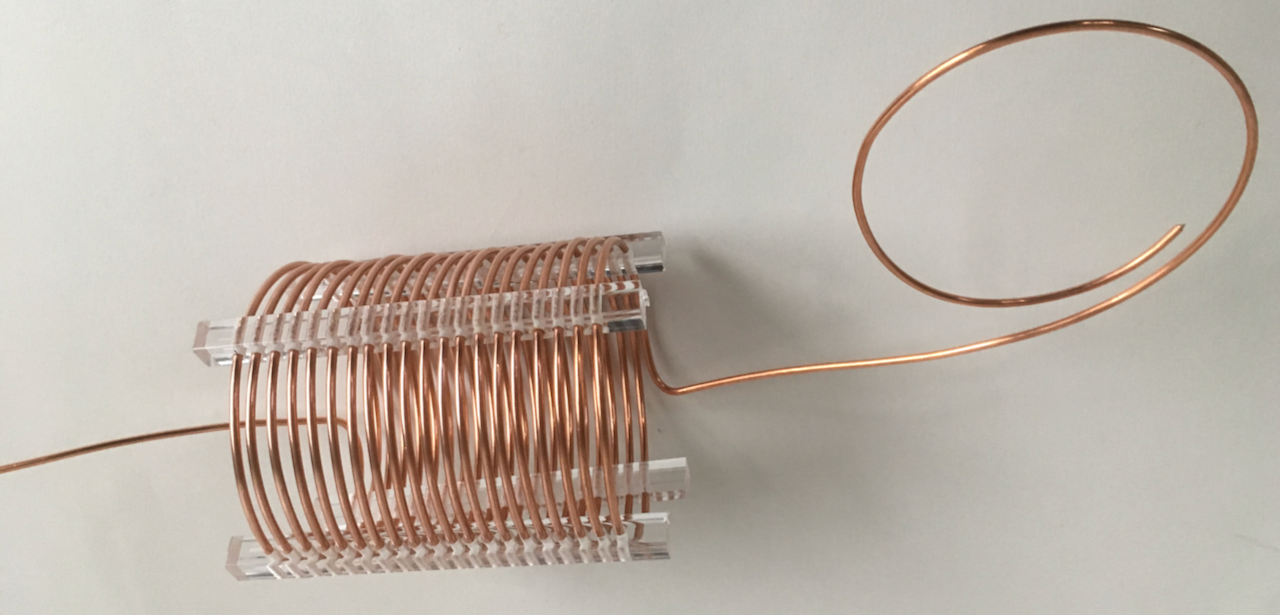
Then, I made coil spacers out of 3/8" square acrylic bar from Tap Plastics, with holes drilled every 1/5".
Wood frame for holding coil spacers while threading wire into spacers:
Threading pre-coiled wire through spacers. This was tedious, by the way.
Almost done. After a point, the wooden frame is no longer needed or useful.
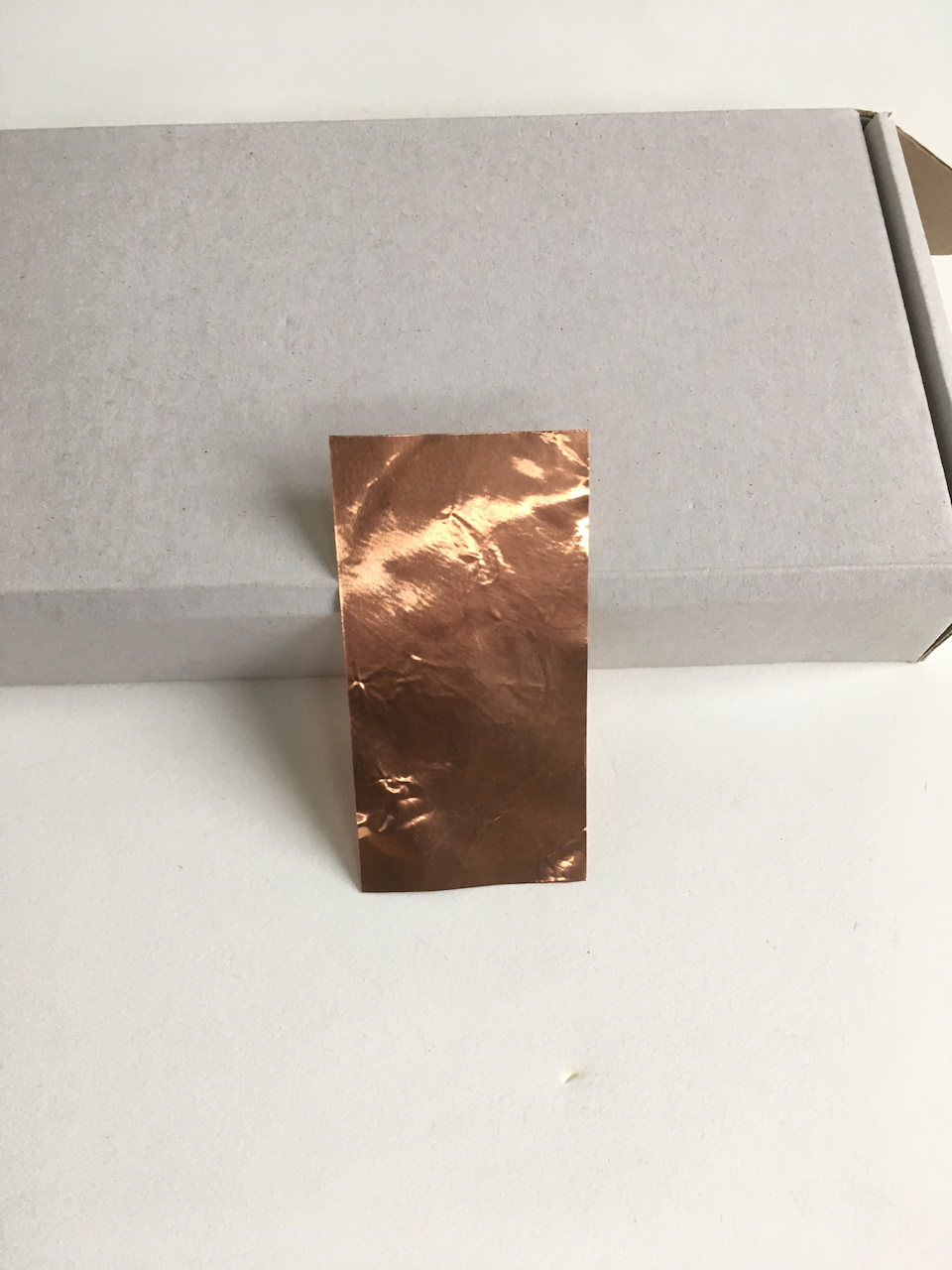
The tabs are made from little rectangles cut from a thin sheet of copper and folded in half around the wire. A 10 cm x 10 cm x 0.1 mm sheet of copper was 91¢ on eBay from China.
The toroidal inductor is wound with 41 turns of 18 AWG 600 volt wire on a T200-6 toroid.
To contact the author, send email.