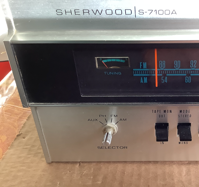
Sherwood S-7100A repair: capacitors, dial lamps, dial cord
Updated 2023-04-17.
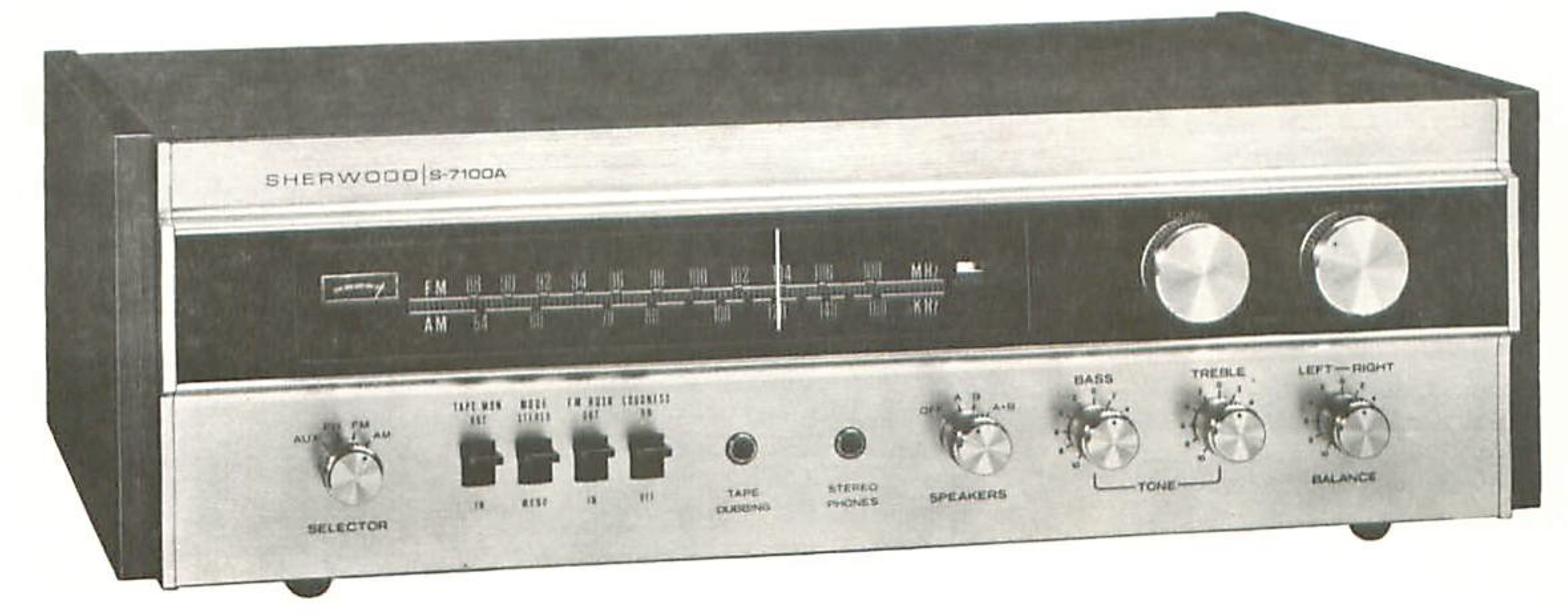
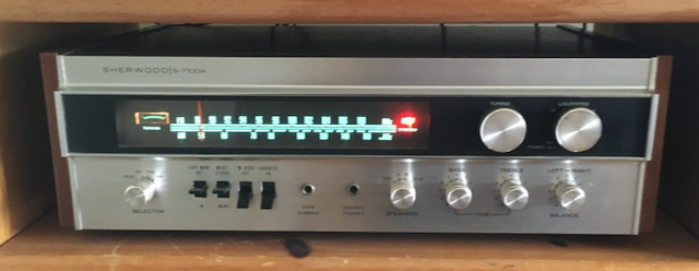
In February 1974, I paid $220 for a Sherwood S-7100A receiver. It was a big purchase for me - in 2021 inflation-adjusted dollars that corresponds to about $1295 - but back then there were no laptops or iPhones for college students to spend money on.
It gave faithful service for about 40 years, but in later years it was increasingly crackly and staticy. I replaced it with an Onkyo TX-8050 tuner in 2011.
The Onkyo crapped out after 9 years. No sound, no nothing. It likely had a bad chip. I just missed out on the special warranty program they had to fix it.
Currently available stereo tuners seemed like they might be more of the same. My old Sherwood, still in the attic, was from the "golden age of audio," so I thought I'd try to refurbish it. One aspect of that "golden age" was that the user manual included a large schematic diagram of the whole thing.
Those things were designed and sold with the assumption that they could be repaired.
Re-capping
The S-7100A had 44 electrolytic capacitors. Electrolytic caps are noted for failing after a few decades. I assumed they were all suspect, and I replaced them all. The service manual provided a useful list of all the capacitors. [Except there might be two misprints in the capacitor list! See below.] The order from Digi-Key came to $23 plus $5 for shipping.
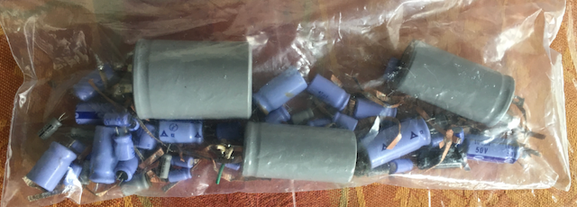
This is what a nasty old leaking electrolytic cap looks like:
There were plenty of them amongst the 44.
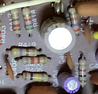
The circuit boards were glorious to work on: each part is identified by part number, right on the board.
One circuit board was accessible from both sides of the chassis without having to unmount the board, so I began there. Using plenty of solder-wick, I removed and replaced each capacitor in turn, carefully noting the polarity. Almost all of the electrolytic capacitors also had the polarity clearly marked, too, but there were one or two that didn't. It was very helpful take pictures of everything before disassembling anything.
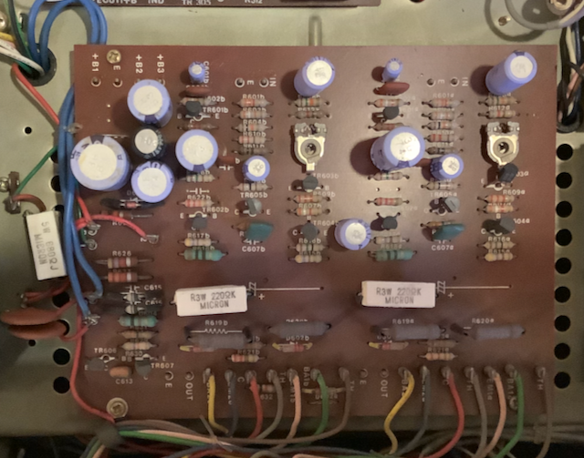
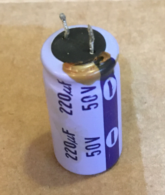
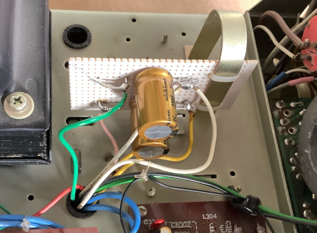
The gold capacitor here is the first one I replaced. The 2021 capacitors were all smaller in physical size than their 1974 counterparts.
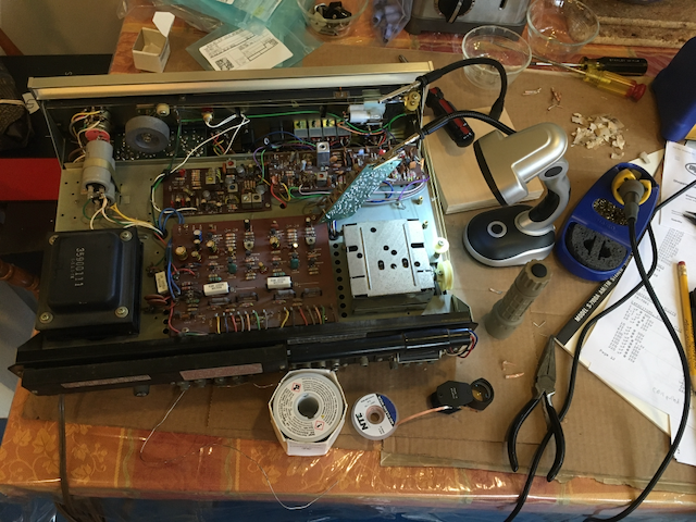
Some of the circuit boards required unsoldering a wire or two and unscrewing the board so it could be tipped up to provide access to both sides. Here's one board held up by a "third hand" jig. Also shown are some of tools I used, plus front edge of the toaster that lives on the kitchen table. That's a Hakko FX888D-23BY soldering station in the upper right corner.
I found that two of the capacitors listed on the parts list were not the same as what I removed from the unit.
| ID | Parts list value | Schematic value | Actual value |
|---|---|---|---|
| C311 | 100 uF @ 16V | 330 uF @ 16V | 330 uF @ 16V |
| C611 | 100 uF @ 35V | 100 uF @ 35V | 47 uF @ 63V |
Unclear whether this was an assembly error, a manufacturing substitution, or a design revision. At the time of the repair work, I used the parts as specified in the parts list with no apparent ill effect. In hindsight, this may have been a mistake.
C311 had two "votes" for 330 uF and only one vote for 100 uF, suggesting there was an error in the parts list. C311 is on the FM MPX board, and FM sounds OK to me, so maybe it's not a problem.
Of more concern is the voltage rating for C611; from my reading of the schematic, the 63V value seems to be correct, in which case using a 35V cap is definitely the wrong thing. Next chance I get, I will replace C611 with a capacitor rated 63V. That still leaves open the question of 100 uF vs 47 uF, but since it's in the power supply circuitry, the value is probably not that critical, and I expect I'll keep it at 100 uF.
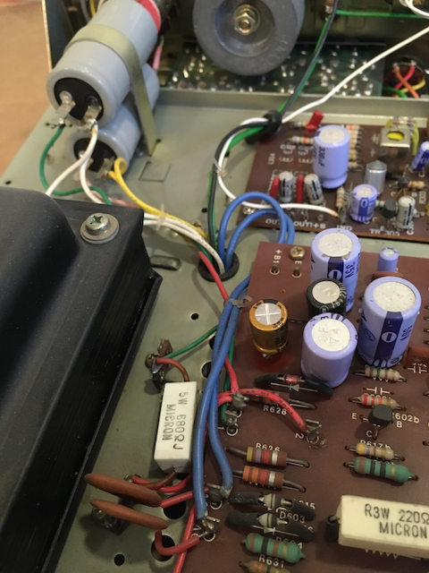
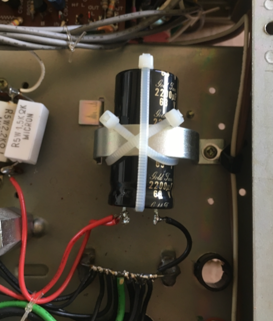
[Update 2022-01-02: The alternative capacitors (100 uF 63v and 330uF 16v) just arrived. Thank you, Mouser, for $3.49 economy shipping to residential addresses! I installed them, and I feel better now.]The original big filter caps were held in place by large clamps.
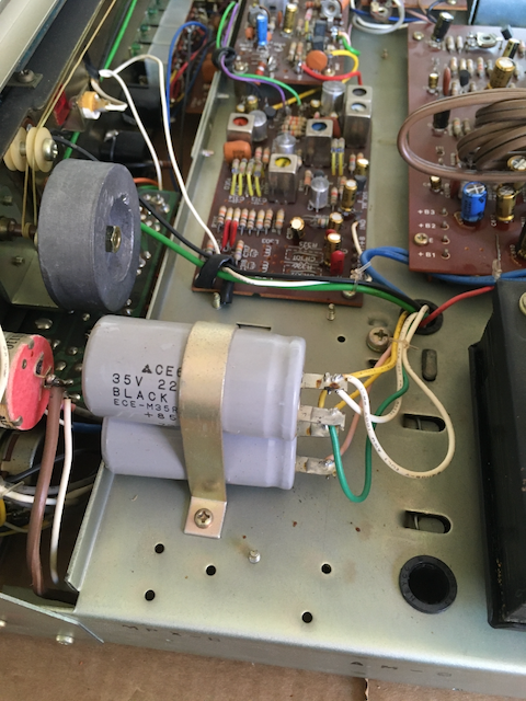
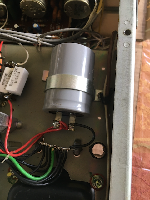
I had to rig up substitute arrangements for the replacements.
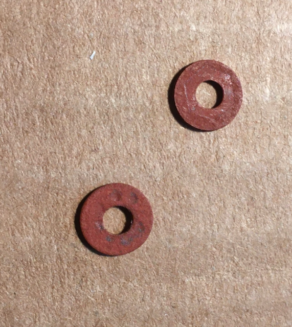
When I was all done, I found, to my dismay, these two insulating washers on the table, with no idea where they came from. I inspected all the screws I had loosened, and didn't see any that would seem to require them.
Nevertheless, I gingerly plugged in the S-7100A, turned it on, and it passed the smoke test. I listened to AM & FM stations with headphones. Sounded good.
Dial lights
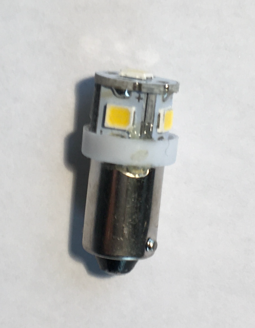
After fifty years, three of the four dial lights had burnt out. Amazingly enough, a search on eBay for "Sherwood s-7100a dial lamps" took me directly here, where for about $10 plus shipping, I got LED replacements for all four.
The meter light is easily accessible and the easiest to change, but it's also the only one still working, so I decided to leave it alone. I'll hold on to the replacement until it's needed.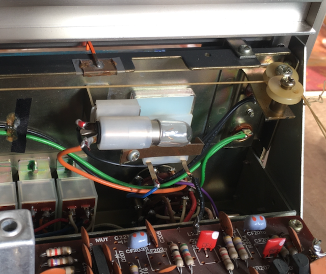
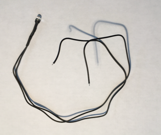
The stereo light comes with wires attached that need to be soldered in. The supplied wires were long enough to reach the appropriate terminals.
The old stereo lamp was held in place by some crusty old glue. Twisting it back and forth broke the glue, and then gentle tugging removed the lamp.
I wrapped some electrical tape around the replacement so it would have a snug fit, and then pushed into place. I didn't glue it; it seemed like the friction fit, plus the positioning of the wires through the existing tape loop would be enough to keep it in place.
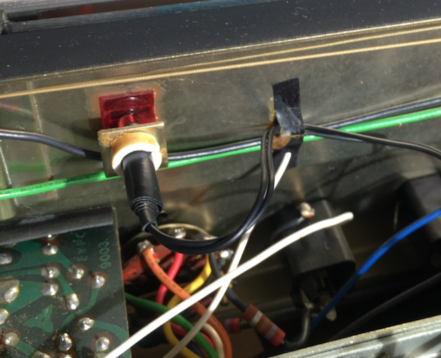
After that, it was simply a matter of following the old lamp wires back and soldering the new ones in place.
I was slightly concerned that since LEDs themselves have polarity, violation of which provides no light and possibly damaged LEDs, that it might matter which way the replacements were installed. In practice, it seemed to make no difference. There is no polarity marked, so it seems they are designed to work either way. (I replaced 3 lamps, and they all worked the first time, so I suppose there is still a 12.5% chance that I was just lucky.)
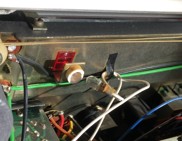
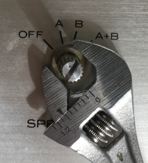
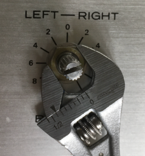
For the remaining two dial lamps, which looked like fuses, I had to remove the front panel. Various Youtube videos of similar components of that era suggested that I would find screws on top and bottom of the panel to undo. No such screws found. It turns out the S-7100A front panel is held on by nuts on three of the front panel controls. After removing all the front knobs, which were of the splined type (no set screws - just tug on them slowly and hope nothing breaks), I found nuts on the selector, speakers, and left-right controls.
Note that first two nuts are smaller than the left-right nut.
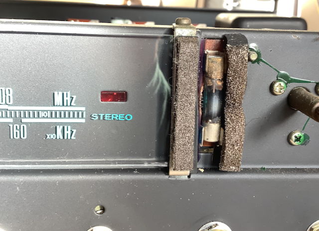
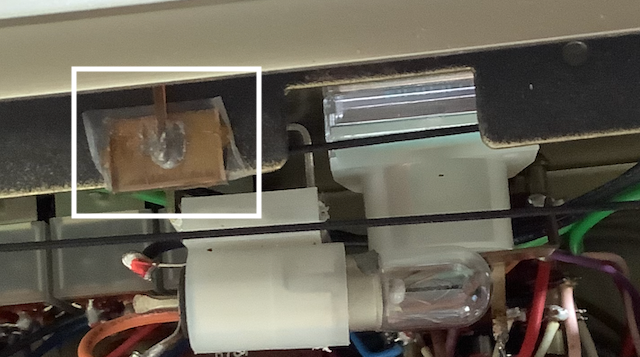
Removing the front panel reveals the fuse-type lamps. The surrounding foam strips are dry and crumbly.
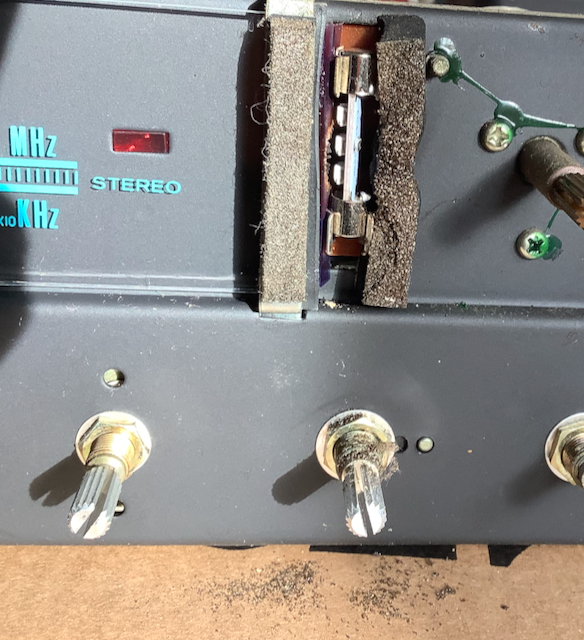
The replacements pop into the holders. They need to be aimed to point towards the dial.
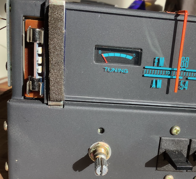
Glowing in all its glory:
Dial cord
The half-century-old dial cord actually worked fine, until someone recently brushed against it with a hot soldering iron.
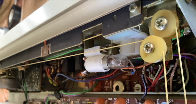
eBay to the rescue again: 12 feet of dial cord, for $8.29 shipping included. I used about 6 feet of it to restring the S-7100A. Here, I took a lot of pictures, to be sure to get the pattern right.
Note, in particular, that this smaller wheel on the right does not seem to participate. Not sure what it's for.
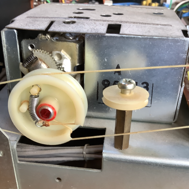
Mystery solved! See Update #2 below.
Here are the other pictures, some featuring the old cord and some the new.
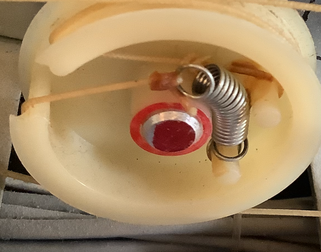
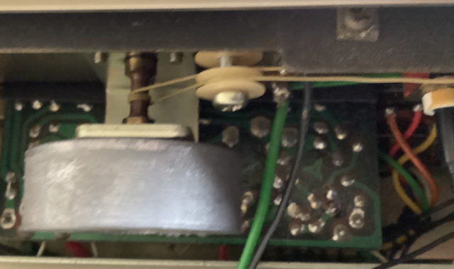
The cord attaches to the pointer via two folded metal tabs on the other side of this part. The part needs to be slid over to the notch to the right, in order to rotate it and free it for access.
Switch and potentiometer
At one point after I reinstalled the S-7100A, the aux selection only provided sound out of one speaker, although the other settings (AM, FM, phono, as well as tape mon) all worked fine. It turned out to be a problem in the switch itself, which was cured by a few moments of vigorous rotation of the switch back and forth.
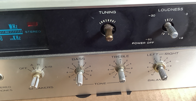
I found there was still an occasional bit of light crackling when the loudness control was turned off, or turned on to a low level. I believe the source of the problem is now only in the loudness control itself. The internet advice for this kind problem varies from dire warnings against the use in potentiometers of cleaning compounds to "Just squirt some good ole WD-40 in there." The least threatening suggestion was simply to spend a few minutes rotating the knob back and forth to knock off any dust or crud inside. I tried that, and with a little bit of effort, I was able to convince myself that it helped. (While doing so, I did not turn it fully counterclockwise to engage the on-off switch; that switch is reputed to be fragile and prone to failure, so while exercising the potentiometer part of the control, I wanted to be sure not decrease the lifetime of the on-off switch part.)
Updates
- After a few months, the Selector switch started making intermittent contact in one channel. Jiggling the switch sometimes provided at best temporary improvement. The problem was solved by spraying the contacts with Hosa D5S-6 CAIG DeoxIT 5% Spray Contact Cleaner. Although I am wary of the indiscriminate use of contact cleaner, this seemed to be a good solution, certainly preferable to replacing a switch with a hairy number of soldered wires.
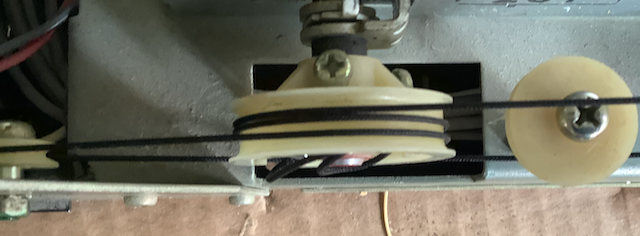
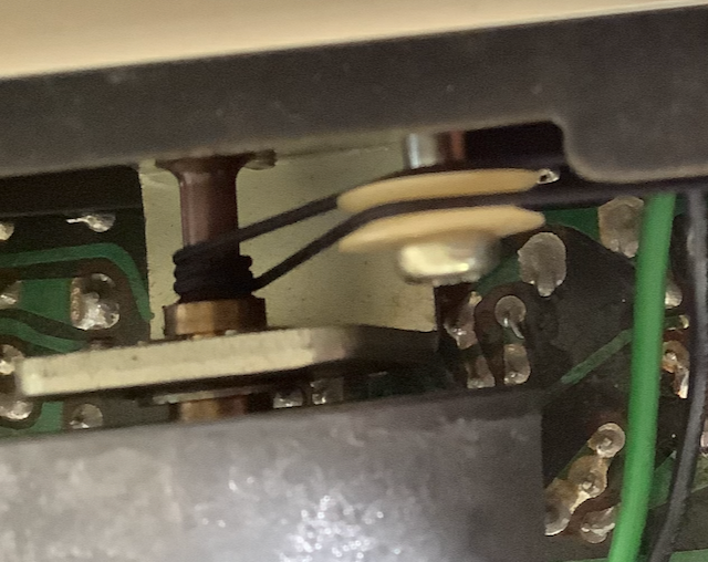
- Answer to the mystery of the unused wheel: A kind reader, John Becker, sent me the following picture and explanation:
"... the small horizontal wheel actually does serve a purpose. Here’s a picture of mine:"
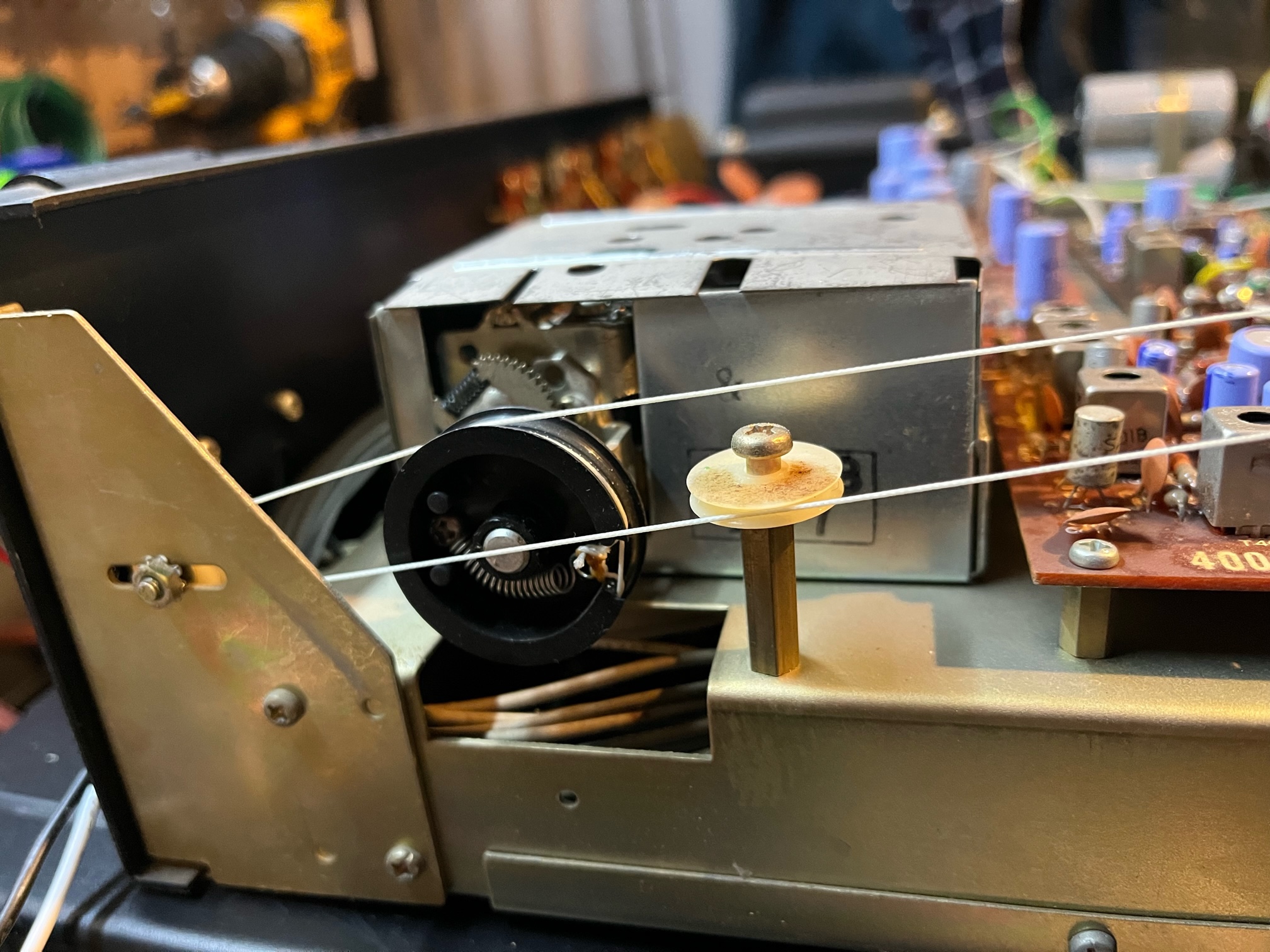
"It holds the cord away from the black (yours is white) wheel that the cord is wrapped around. From there it goes to the bottom of the small wheel near the very back."
To contact the author, send email.